We just helped one of our members with his motorcycle. The plan is to update an older Triumph with a Microsquirt engine control unit to make the bike a bit more adjustable and debuggable. Triumph has designed a pretty complex system with several MAP sensors and two lambdas and such. Now the system will be a lot simpler, as the bike will run only with the bare minimum amount of sensors.
Microsquirt is a small version of Megasquirt, so it suits motorcycles perfectly. However, during the installation we came to the conclusion that it would be nice if the adjustments for the ECU wouldn’t need a wired serial link. The serial link is already wired on the off-the-shelf wiring harness but having a cable for the serial link with its own connector makes the ECU box harder to hide and might cause some reliability issues later, as the connector is only needed in the adjustment phase, but it will be sitting there getting water and grime in it for the rest of the time.
So, we decided to add Bluetooth connectivity to this ECU unit. The modification was easy enough, but we had to combine several sources of information to succeed, so we decided to write our own instructions here, if someone else would like to do the same. Our main resource was https://www.youtube.com/watch?v=Gk5p7T2CyGE
So, first you need:
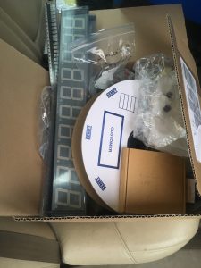
- Microsquirt ECU
- HC-05/HC-06 Bluetooth module with a breakout board
- Arduino
- jumper wires
- a breadboard
- soldering stuff + hot glue + shrink tubes + zip ties etc.
Basically, the procedure is really easy. First, we must get the Bluetooth module into AT mode, then change the baud rate, rename the module’s Bluetooth device name and set a PIN. This is also covered in this instructable: https://www.instructables.com/id/AT-command-mode-of-HC-05-Bluetooth-module/ After the module is set, just solder it to the Microsquirt and you’re done.
First, we set the module to the AT mode. To achieve this, the key pin on the module has to be set up while the module boots. In our case, the module was in a plastic shrink wrap, so it was impossible to make any contact with the key pin. So, locate the key pin on the module, and cut a hole in the wrapping. The key pin is the first pin on the left side of the module, if looking the module from the antenna end with antenna facing upwards.
Next, connect the module to the breadboard, and use jumper wires to give the device. Connect Arduino 3.V and ground to the corresponding pins of the BT module. Connect serial pins so that RX pin of the module goes to pin 11 of the Arduino and TX pin of the module to the pin 10 on the Arduino.
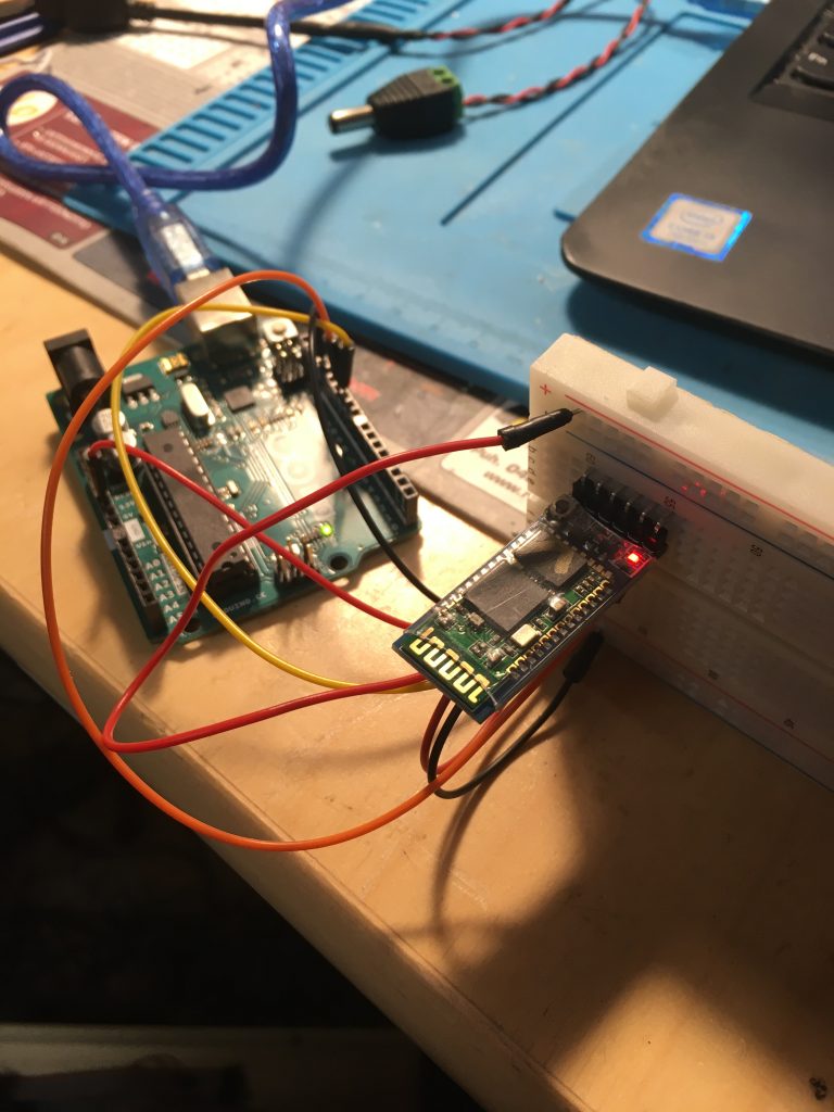
Add one jumper wire to the strip that is connected to the 5 volt pin on the Arduino. Now, when you connect the Arduino to the computer so it boots up, simultaneously touch with this wire the exposed key pin and hold. If the module starts blinking in two second cycle, congratulations, you are now in the AT mode.
Next, we need a serial software on the Arduino. Use this modified version of the Serial example:
/////////////////////////////////////////////////////////////////////////////////////////////////////////////////////////
#include SoftwareSerial mySerial(10, 11); // RX, TX
void setup() {
Serial.begin(9600);
pinMode(9,OUTPUT); digitalWrite(9,HIGH);
Serial.println("Enter AT commands:");
mySerial.begin(38400);
}
void loop()
{
if (mySerial.available())
Serial.write(mySerial.read());
if (Serial.available())
mySerial.write(Serial.read());
}
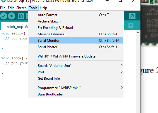
/////////////////////////////////////////////////////////////////////////////////////////////////////////////////////////Using Arduino IDE, make sure your board is in Arduino Uno mode, upload the code, boot the Arduino and make sure that the BT module is still in the AT mode. Next, back in the Arduino IDE, use the serial monitor. In the serial monitor window, set baud rate to 38400 baud, and the linefeed to “Both NL & CR”. Now, pressing enter, should see “Enter AT commands:” prompt.
Next, write “AT” to the prompt, and the BT module should answer with “OK”. NExt, issue AT+NAME=<yourdevicename followed with an enter and AT+PIN=<yourpincode> <ENTER> to set the BT device name and the PIN. Both commands should give an OK reply. Then, set the device baud rate to match the Microsquirt. So, issue a command AT+BAUD=19200 <ENTER>. It also should return an OK. Now you’re done with the configuration part.
Next, open up the Microsquirt box. It should be just 8 Philips screws, four on the both sides.
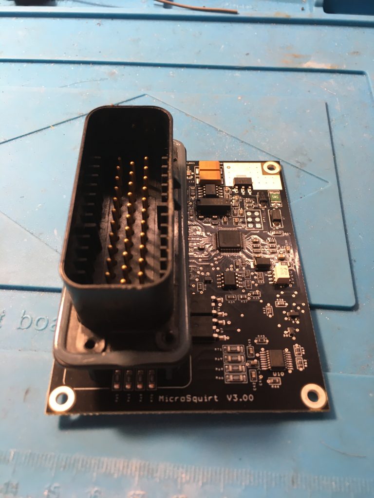
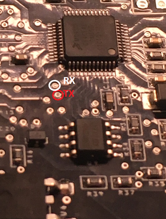
Locate the pinheader and the two vias (round holes on the circuit board) just next to the controller in the middle of the board. The pinheader can be used to power up the module, so solder a jumper wire with a suitable end to go with the BT module breakout header to the pins 2 and 6. You can see number 1 printed on the circuit board, so that’s the pin one, one just next to that is 2, the ground pin. Pin number 6 is the last one, so it’s in the same row as the ground pin, but on the other end. That’s where you solder the VCC wire.
Next, the two vias are a bit tricky. You should take two jumper wires and expose their ends, apply a bit of solder and put them on the correct vias and use your solder tip to make a connection. Use the photo below to locate the correct position of the wires.
Now it’s a good moment to test if you can connect to the module if the Microsquirt is powered on.
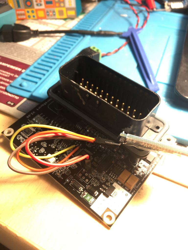
Last, just apply hot glue over the soldering points, put some fresh shrink wrapping over the module and use zip ties to fasten the wires to the connector feet. A good place to put the module is under the big Microsquirt connector, just other side of the connector from where you made the solder points. On that side, the module can be easily glued fast and the possibility of accidental connections is minimized. Just put the cover back on and screw it tight. Now you are done, enjoy!